Add clearance between two printed parts
Treat clearance as a relationship between two surfaces, then test that relationship in the same orientation and material as the finished parts.
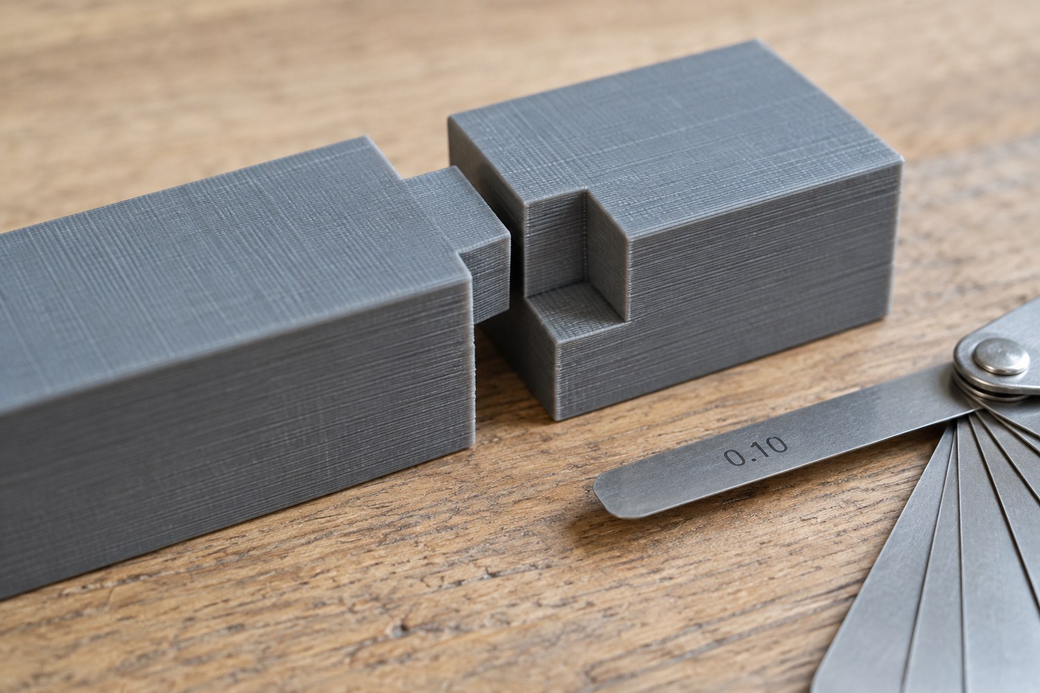
Two parts drawn with exactly matching boundaries may not assemble as intended after printing. The question is not just how large the hole is, but how the mating surfaces will be made, finished and used. A removable roof, a sliding tray and a permanently glued locating pin need different kinds of fit.
Write the intended behaviour before choosing a number. Should the part drop into place under its own weight, slide with light resistance, or remain fixed after assembly? Decide which direction it enters and where it stops. An apparently adequate opening can still be difficult to use if fingers cannot reach it or a nearby detail blocks the insertion path.
Distinguish total difference from clearance per side
For a simple centred square insert, the difference between the opening width and insert width is shared between opposite sides. In a hypothetical design, a 20.0 millimetre insert inside a 20.6 millimetre opening has a nominal 0.6 millimetre total difference, or 0.3 millimetres on each side when centred. These are drawing dimensions, not a recommendation for a particular printer.
Use the same language in your notes and modelling parameters. A field called clearance is ambiguous if one revision treats it as the total difference and another doubles it for both sides. Label the dimension explicitly, such as side gap or opening width. Check the depth as well: a peg can have adequate side clearance but bottom out before the joint closes.
Make a test that resembles the real joint
Create a short section containing the actual mating shapes. Keep the same intended material, printing orientation and relevant preparation settings. A vertical round hole is not an equivalent test for a horizontal square socket merely because the nominal width is similar. Include enough surrounding material for the test to behave like the real part.
Print several clearly labelled variants around your proposed fit. Change one dimension deliberately and keep a record of which number belongs to which sample. Evaluate the cooled and appropriately prepared parts, not an unfinished piece held against a screen. Remove only the cleanup that will also be performed on the finished joint.
If painting or coating is planned, include that stage in a second test. Paint on both mating surfaces changes the relationship. It may be simpler to keep the contact area unpainted, but that decision belongs in the design and finishing plan. Do not compensate by forcing a delicate model together; a fit that requires excessive pressure is giving useful feedback.
Check alignment as well as freedom of movement
A loose part can assemble easily and still sit crooked. Look at the visible seam, the alignment of nearby edges and any tendency to rock. Consider whether a broad locating lip or a separate alignment feature would guide the part more reliably than simply reducing every gap.
For a removable terrain roof, test lifting it by the intended grip point and replacing it without touching fragile details. For a sliding drawer, test the whole travel rather than only the first few millimetres. Record the successful combination of geometry and process, and retain the test piece with its label. The result is evidence for that joint under those conditions, not a universal tolerance to apply to all future models.
Read an uneven fit as a clue
Suppose a rectangular lid slides over one short end of a box but jams when lowered over the other. Do not immediately increase the clearance parameter everywhere. Compare the two ends, inspect for leftover support or a raised edge, and check whether the lid and body are straight. A local obstruction, a dimensional mismatch and a distorted large part need different responses.
Mark the orientation that produces the problem with removable labels. Try the lid in the intended direction only, then compare the relevant dimensions at several positions. If you change the design, alter the feature supported by that evidence. Keep the earlier sample so that the next test can be compared directly. Otherwise, repeated sanding and redesign may remove the evidence without revealing which change helped.
For a joint that will be painted, keep one unpainted control sample. Comparing it with the finished sample separates the geometry question from the coating question. The useful result is a short explanation of why the accepted joint works, alongside the actual dimensions and process. That record is more informative than a single clearance number detached from its test.
Another detail to explore
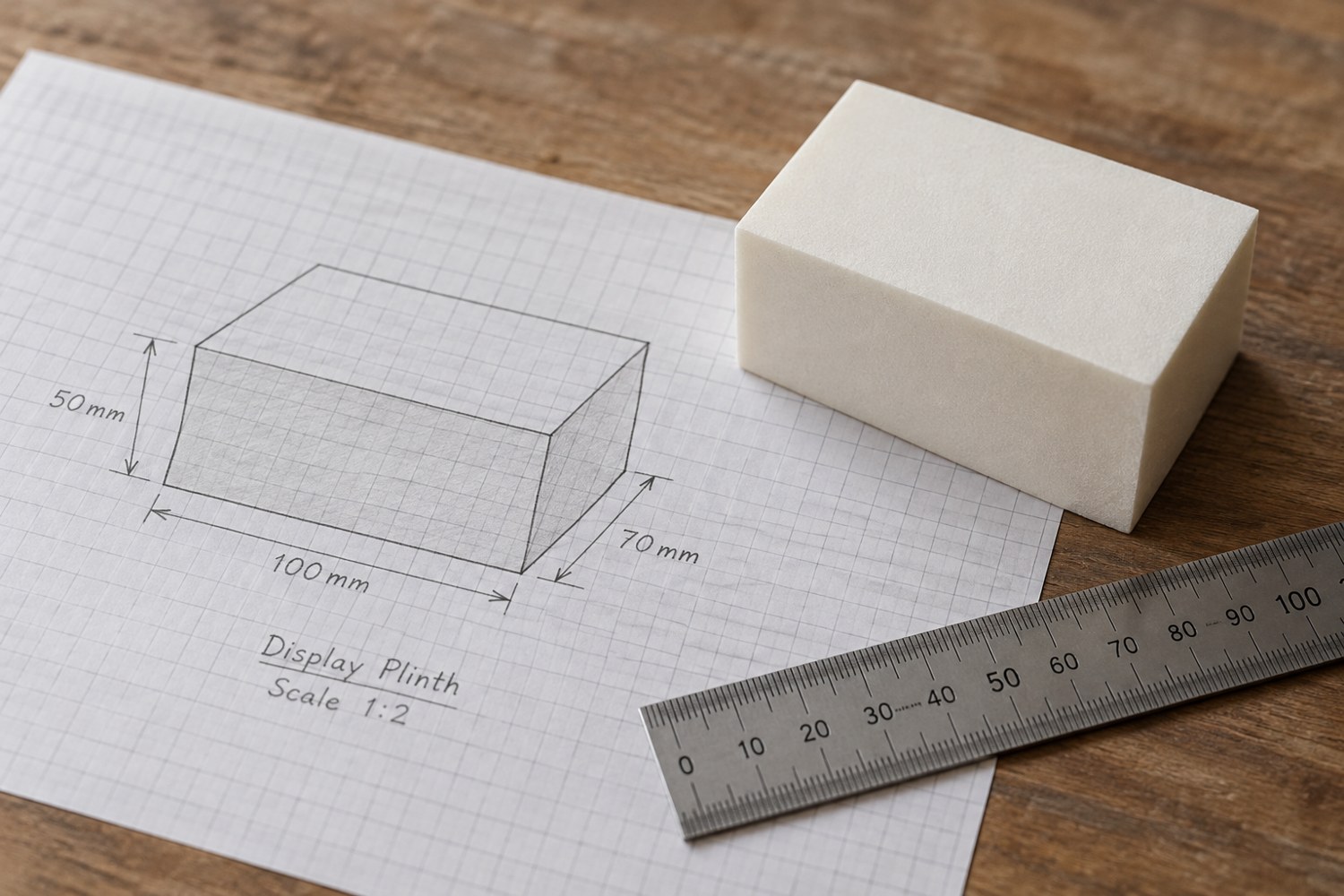
Start a model with dimensions instead of details
Build a short dimensional brief before adding bevels, textures or decorative features. It gives every later modelling decision a reference.
Read article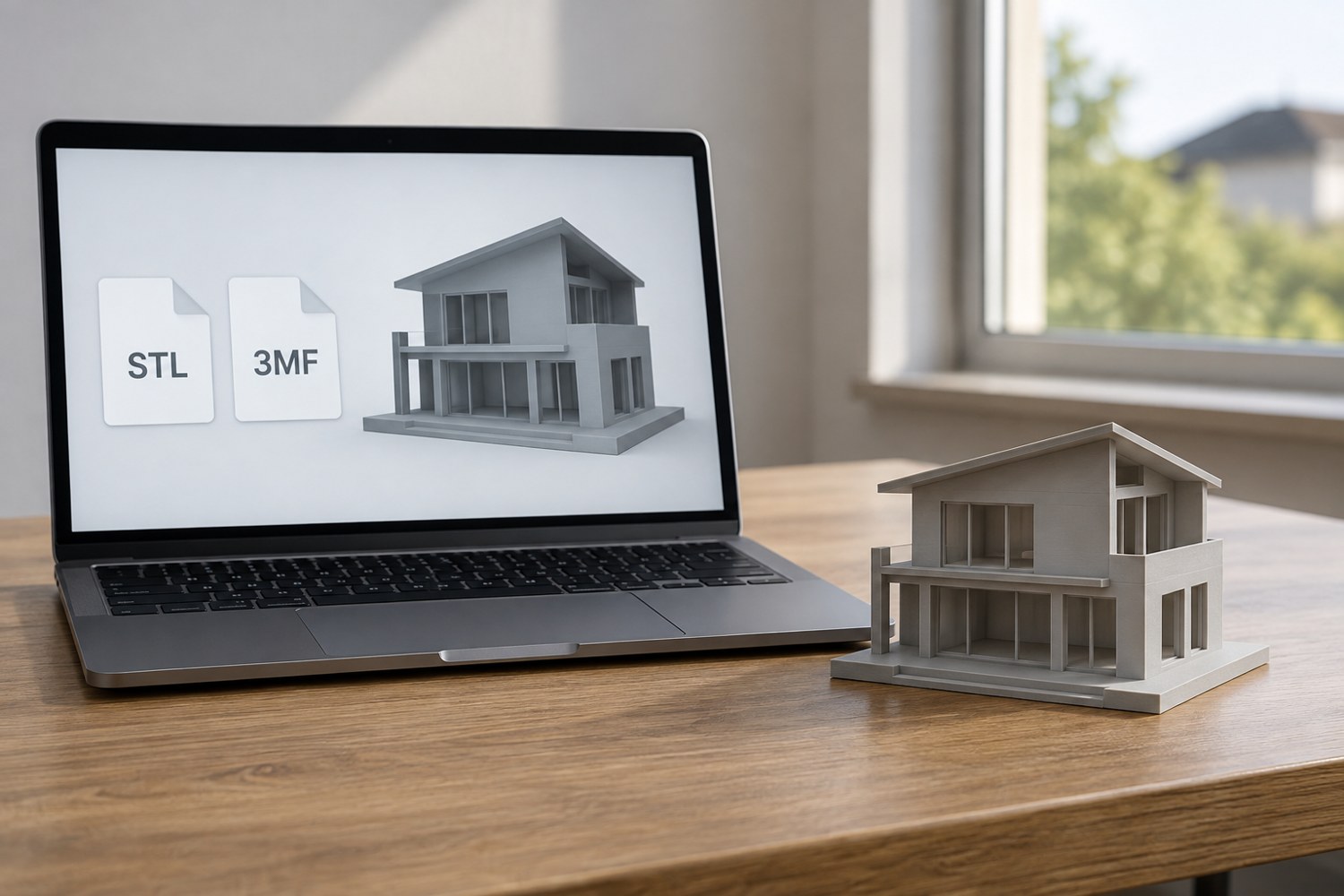
Understand STL and 3MF when sharing a print project
An STL mesh and a saved 3MF project can carry different information. Decide what a recipient needs before choosing the file to send.
Read article