Choose an orientation for a printed bracket
Balance the visible face, layer direction and assembly access on a non-critical bracket.
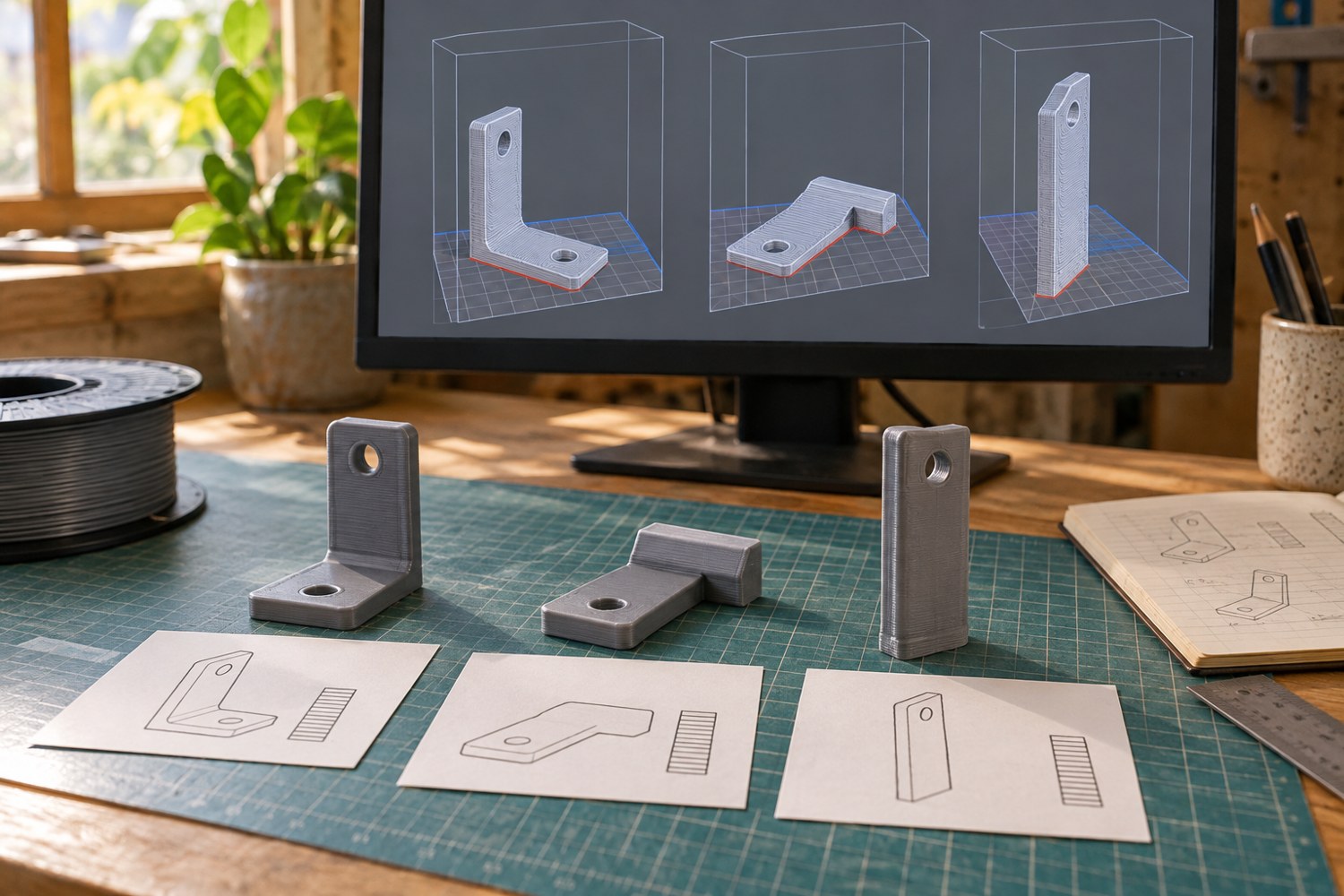
The broadest flat face is a sensible first candidate for placing a bracket on the build plate, but it is not the whole decision. Orientation changes where supports touch, how holes are formed and how the printed layers run through the part. Start by drawing the bracket in the position in which it will be used. Mark the fasteners, the contact surfaces and the direction in which the attached object will push or pull.
This is a planning exercise for light-duty model or display hardware. A printed bracket supporting people, heavy objects or safety-critical equipment needs appropriate engineering and validation. A neat sample and a hand pull are not a load rating. For a shelf-mounted miniature sign, however, thoughtful orientation can still prevent obvious assembly problems and unnecessary cleanup.
Make three candidates
Place copies of the bracket on its back, side and base in the slicer. Do not immediately optimise each one. First compare what each orientation asks the printer to create. Which holes are vertical? Which underside needs support? Does a thin arm begin above empty space? Is the face that must sit flush against another part now covered in support contact marks?
Add a simple arrow to a paper sketch to show the likely loading direction. Layered parts can respond differently depending on orientation, so avoid assuming identical behaviour after rotation. If the bracket's intended load or consequences exceed a decorative use, consult a competent designer rather than extrapolating from a hobby test. More infill is not a universal answer to an unsuitable joint or orientation.
Compare cleanup access. A support under an open ledge is easier to reach than one packed inside a narrow screw recess. Check that the tool you intend to use can actually enter without damaging the surrounding wall. If every orientation creates a bad recess, change the model: a separate cap, a different fastener approach or a revised opening can be more useful than a complicated support arrangement.
Test the joint before the complete assembly
Print a short representative section containing a mounting hole and the adjacent arm. Use the intended fastener and mating surface, with the equipment unpowered where relevant. The test should show whether the screw head seats, whether the driver reaches it and whether the bracket sits flat. It does not establish the long-term strength of the full design.
If the bracket will be painted, keep paint away from surfaces whose fit you have already checked, or repeat the fit after finishing. A narrow recess that accepts a screw before primer may become inconvenient afterwards. Write down which surface faced the plate so that a later reprint does not quietly adopt a different orientation.
Choose the candidate that suits the actual assembly, not the one with the shortest estimate alone. Saving a small amount of printing time is unhelpful if every part then requires careful filing on its reference face. Keep the finished bracket identifiable as a particular model revision and material. When the intended use changes, revisit the design instead of assuming the original orientation remains suitable.
A useful comparison sheet can have one row per orientation and columns for the contact face, screw access, support removal and the visible side. Give each entry a concrete observation, such as ‘support touches the mounting face’ or ‘driver cannot enter after assembly.’ Avoid a single quality score that hides why one candidate is unsuitable. If two orientations are otherwise comparable, the one with a cleaner reference surface may reduce uncertainty during installation.
Also decide how the bracket will be replaced. A decorative display can change over time, and a bracket trapped behind permanently glued scenery may be inconvenient to inspect. A separate accessible fastener can make the printed part a replaceable component. That service access is worth including in the original orientation decision because it determines which recesses and surfaces must remain usable.
Another detail to explore
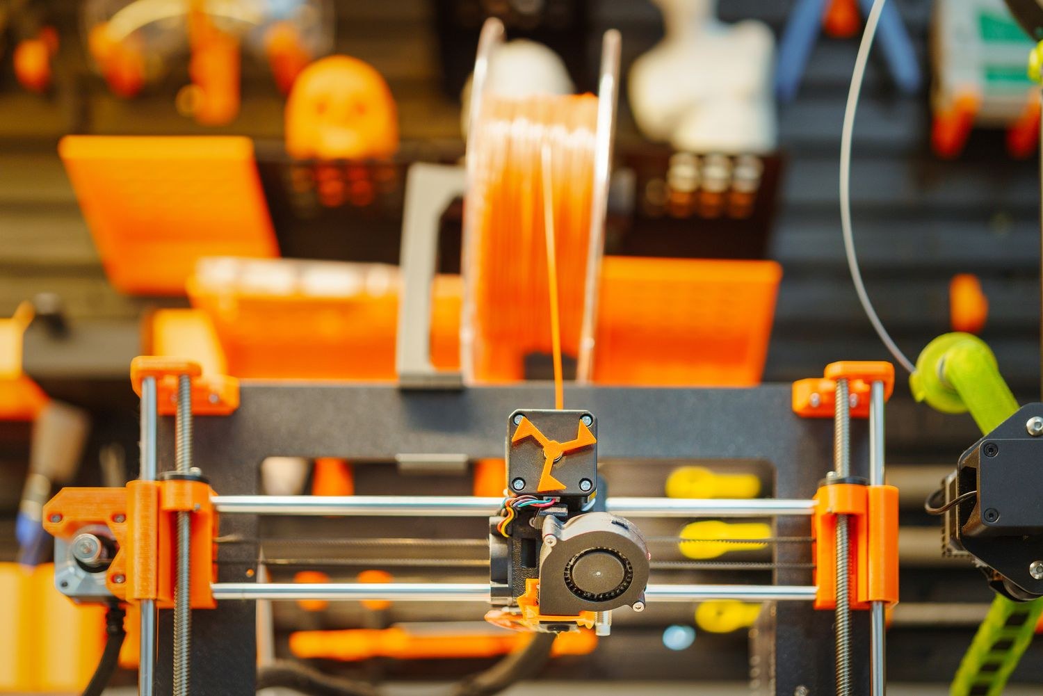
Choose a first 3D printer around the objects you want to make
Start with three objects, their dimensions and the space available for making them. Those decisions narrow the printer search before speed claims do.
Read article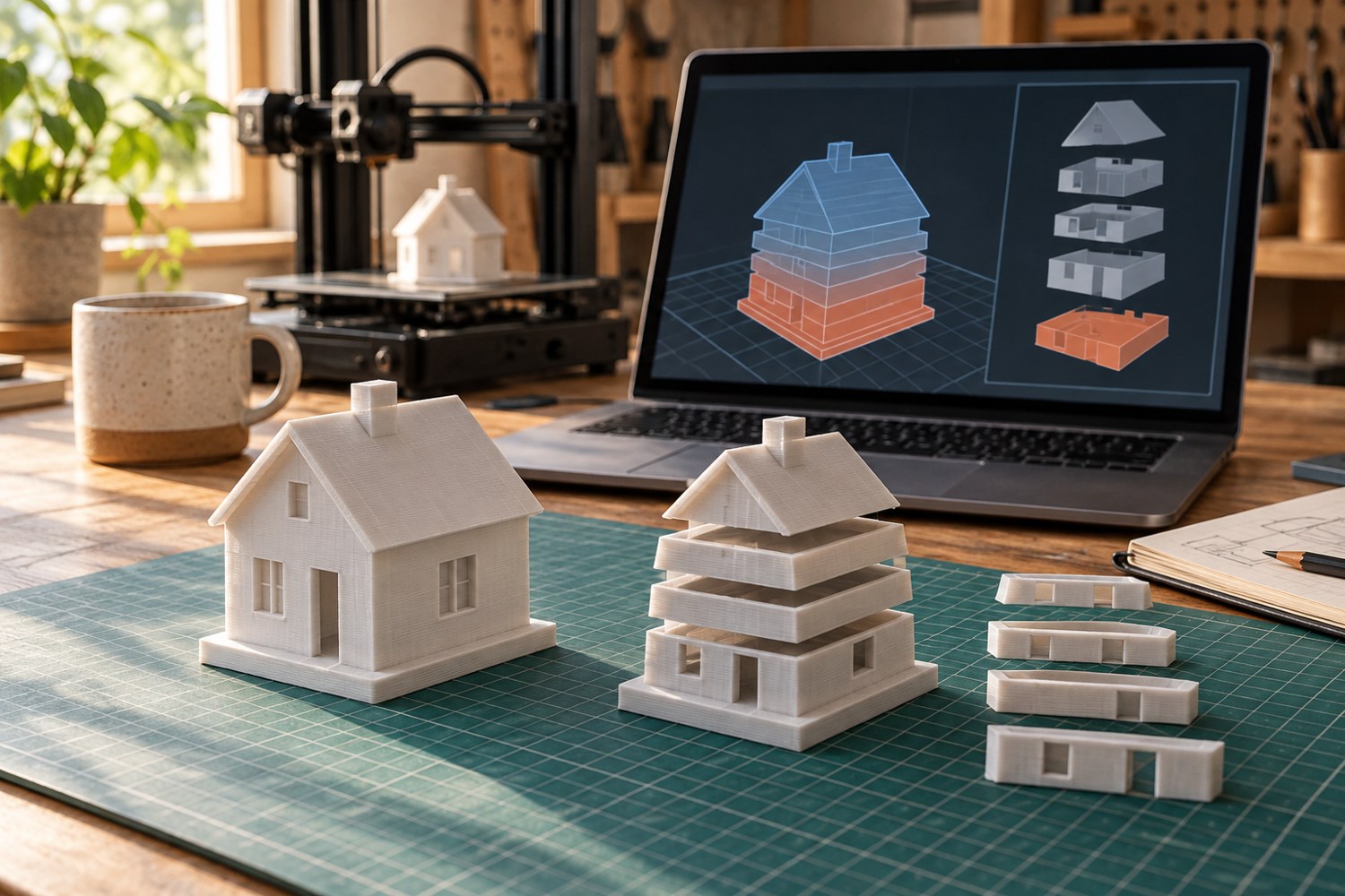
Read a sliced preview before starting a print
Read the toolpaths, first layer and delicate features before a file reaches the printer.
Read article