Use a measuring caliper for model dimensions
Measure the feature you need, repeat the reading and keep measurement separate from design clearance.

A caliper can help turn a vague fit problem into a useful dimension, but only if the contact points are chosen carefully. Decide what you are measuring before closing the jaws. The outside width of a box, the inside opening of its lid and the depth of a recess are different measurements using different parts of the tool.
Clean the measuring faces and check that the tool reads correctly when closed, following its own instructions. Mitutoyo recommends checking zero, using light contact and repeating measurements with proper alignment. Do not squeeze a soft or thin printed wall until the number becomes convenient. The force used can change the object being measured.
Find a meaningful reference surface
Avoid placing the jaws on loose strings, support scars or a raised seam when you want the underlying dimension. Record the condition of the surface. If a brim must be removed before assembly, remove it as planned and measure afterwards; if you are investigating the brim itself, preserve it and name that distinction.
For a rectangular piece, measure at several locations rather than assuming one reading represents the whole object. A base can be wider near the bottom or a wall can taper. Keep the readings associated with their locations. An average alone may hide the one region that prevents the part from fitting.
For an opening, align the inside measuring faces with the intended direction and avoid rocking into an artificial maximum. Repeat the reading after removing and repositioning the tool. If the values vary noticeably, investigate the surface and technique before recording many decimal places. Display resolution is not the same as the uncertainty of a measurement on a textured print.
Turn the result into a design decision
Write the measured dimension separately from the clearance you intend to add. If a component measures a particular width, the cavity may need additional room for assembly, finish and variation. The amount depends on the fit and printing process. Do not quietly add that allowance to the measurement and later forget which number was observed and which was chosen.
Use a labelled sketch to show the direction of each measurement. Include units and identify whether a gap is per side or total. This is especially valuable when sharing a model with someone else: a number without its contact surfaces can be interpreted in more than one way.
Check a proposed clearance with a representative printed coupon before making the entire enclosure. Keep the caliper record with that sample and note any sanding or coating applied afterwards. The tool supplies dimensions, while the fit test supplies evidence about assembly. Using both prevents a precise-looking number from becoming a substitute for checking whether the actual parts work together.
For a pair of parts, measure and label them together. A cavity width written on one page and a matching insert width written elsewhere can easily be confused with a later revision. Put both numbers on the same sketch and identify the measurement direction. Add the observed fit as a separate note, such as free sliding, catches at one corner or cannot enter. This preserves the difference between dimensional evidence and the result of assembly.
Store the tool protected from abrasive dust and follow its care instructions. Before the next session, repeat the basic condition and zero checks. A caliper left among sanding scraps may need attention even if its digital display still turns on normally.
Another detail to explore
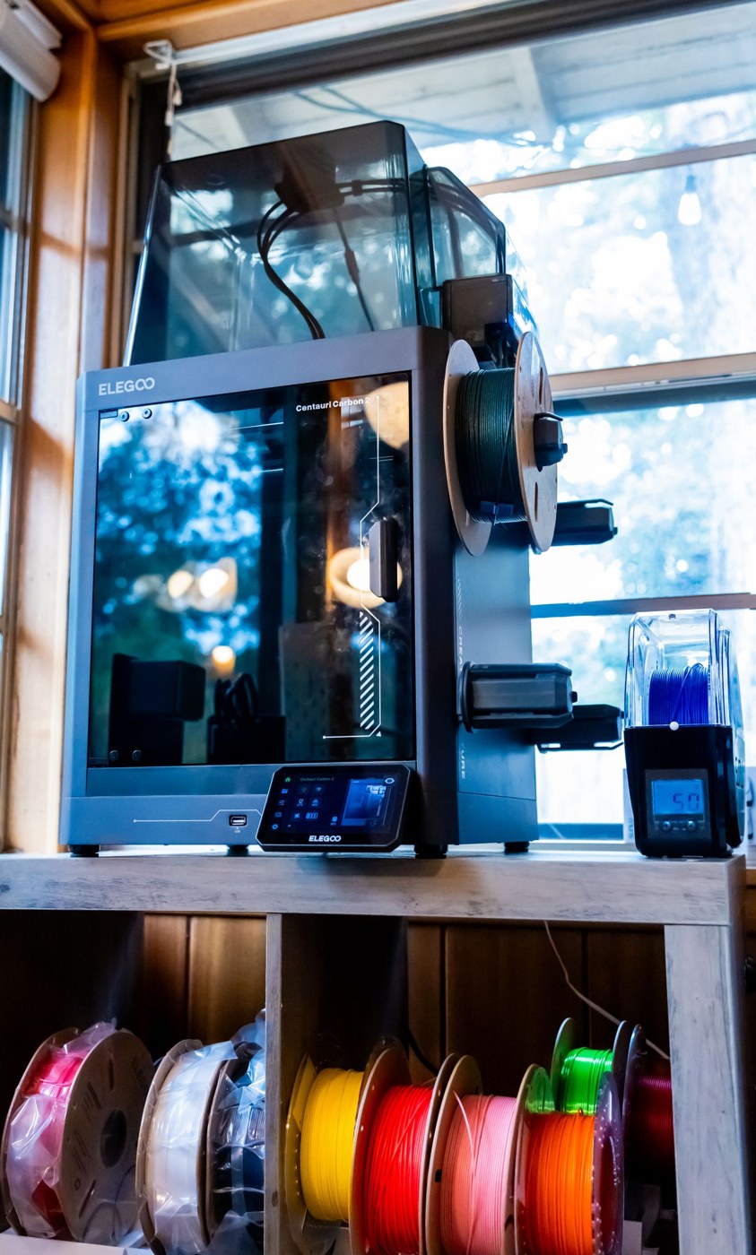
Store filament with a label you can actually use
Keep material identity, opening date and profile information with the spool through storage and use.
Read article
Choose between PLA and PETG for an indoor model
Choose material around handling, shape and finishing rather than treating one polymer as a universal upgrade.
Read article