Arrange modular terrain so tiles meet cleanly
Define a common edge profile and test several tile arrangements before adding texture or connectors.
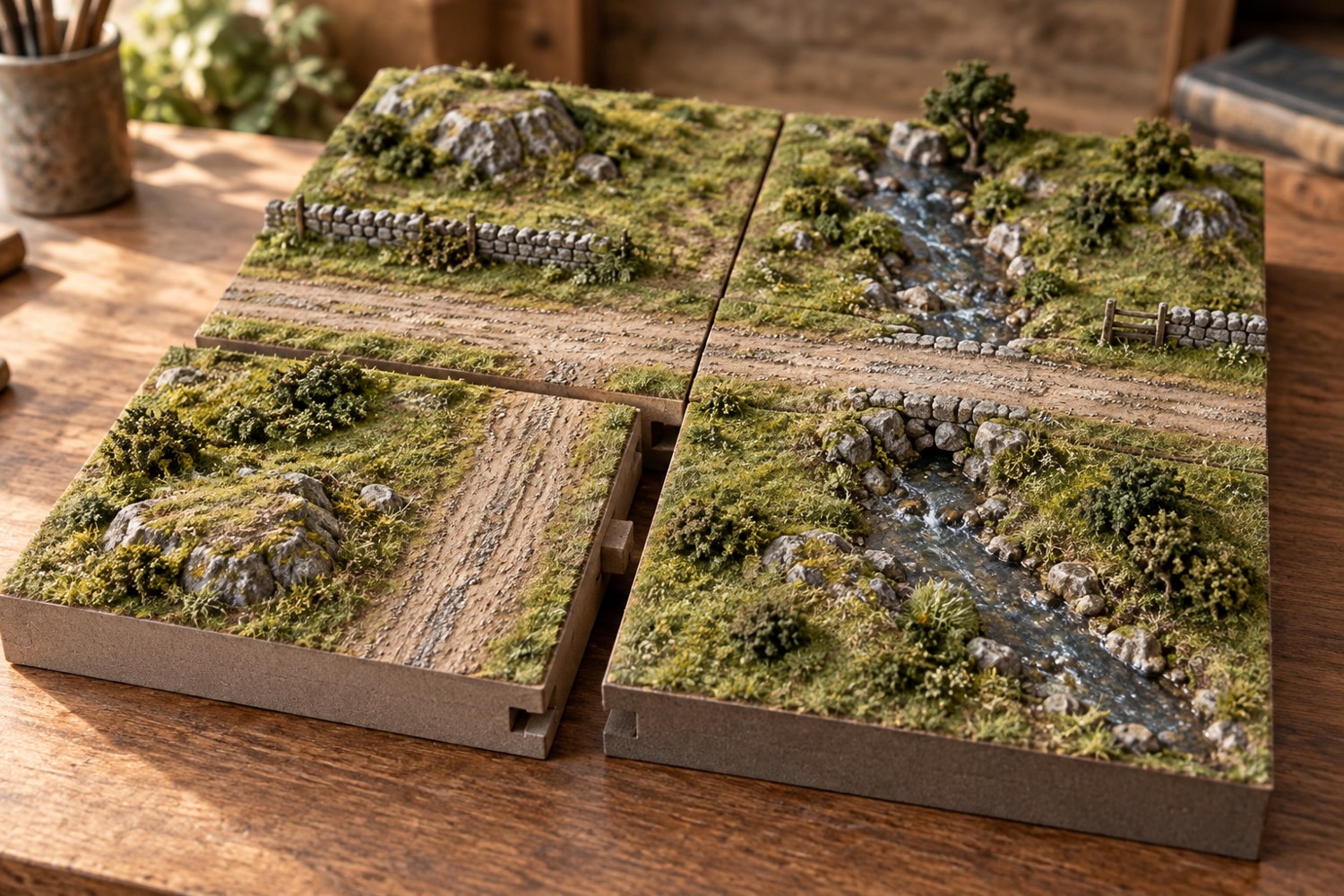
Modular terrain fails most visibly where two attractive tiles meet. A road jumps sideways, a river changes width or a thin layer of scenic material holds the boards apart. Treat the edges as shared interfaces. The centre of each tile can vary, but anything crossing a boundary needs agreed positions, heights and widths.
Draw a master edge on card at full size. Mark the base thickness, ground level and the centre of each crossing. Use this same reference for every tile rather than measuring from a partly finished neighbour. Include a plain edge option so a tile does not force a road or river into every possible arrangement.
Prototype a pair and a corner
Build two undecorated tiles first. Put them together on the surface where they will be used and inspect the join from above and from table height. Rotate one through every permitted orientation. A connector that works in one direction may collide in another. Then place four rough tiles in a square; this reveals accumulated dimensional error that a single pair cannot show.
Choose whether the system is rotational or directional. A directional tile can carry an arrow underneath and have different north and south edges. A rotational system needs compatible edge features wherever a tile may turn. Neither is inherently better, but mixing the assumptions creates layouts that look interchangeable and then refuse to connect.
Keep scenic texture away from bearing surfaces and locating features. Mask those zones while applying ground material, then remove loose grains before trial assembly. Do not rely on compressing vegetation between edges. It can prevent the bases from sitting together and may tear when they separate.
Hide the seam without locking the layout
A removable strip of grass or a loose wall can soften a join, provided it does not become essential to every configuration. Make such pieces identifiable and store them with the set. For roads, align the centre and surface height first; colour variation is easier to disguise than a physical step.
Record the finished edge dimensions and photograph an acceptable join. Use that reference when expanding the collection months later. Check new tiles against the master, not only against the latest addition, so small errors do not drift across the set. Before final painting, assemble the widest layout you expect to use and slide a straight reference across the joins. Correct rocking or uneven support while the surfaces are still accessible.
Road and river intersections
Crossing features need rules beyond their centre position. For a road, record surface width, verge width and height above the base. For a river, record channel width, bank shape and the level of the represented water. A river that meets at the correct centre can still produce an obvious shelf if one tile has a deeper channel.
Make a small edge gauge that includes these relationships. Hold it against each unfinished tile and again after painting. Label its orientation and keep it with the set. If a future expansion uses a different base material, the gauge gives you a shared target without requiring the old tiles to become measuring tools.
Think about termination pieces as part of the collection. A road can leave the board or end at a building, while a river may need a bank or shoreline section. Without those options, every new layout can be forced into the same closed loop. Sketch several complete arrangements using paper squares and include the minimum set of endings that makes them work.
A connector should locate the tile without carrying unsupported weight across a gap. Place the tiles on a suitable flat surface and check that each one rests securely. If a board is warped, stronger connectors may merely pull the neighbouring board out of alignment. Solve the base support before decorating the interface.
Another detail to explore
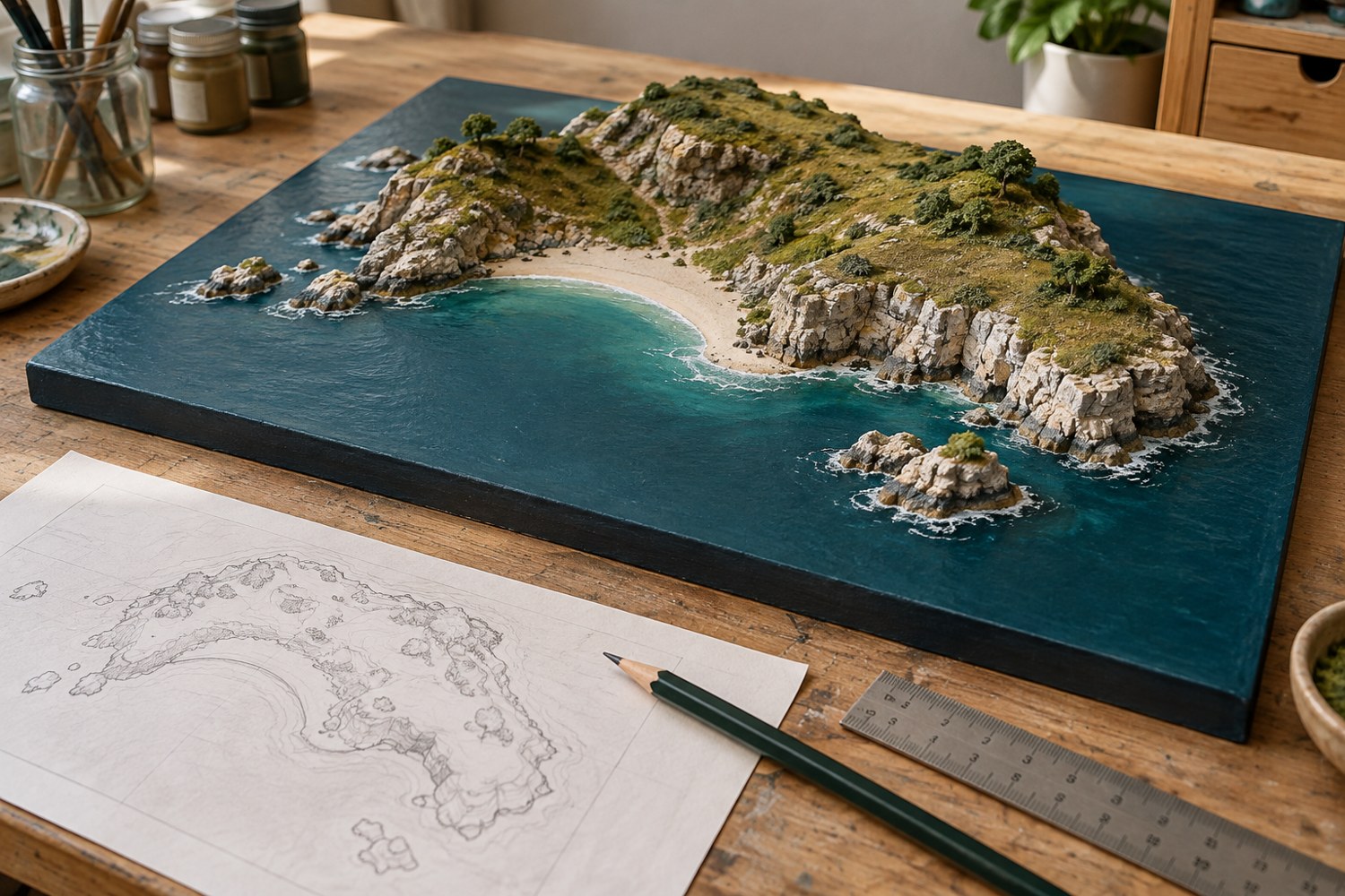
Plan an island diorama before building the coastline
Turn an island idea into a buildable composition by deciding the viewing angle, scale, shoreline and assembly order on paper first.
Read article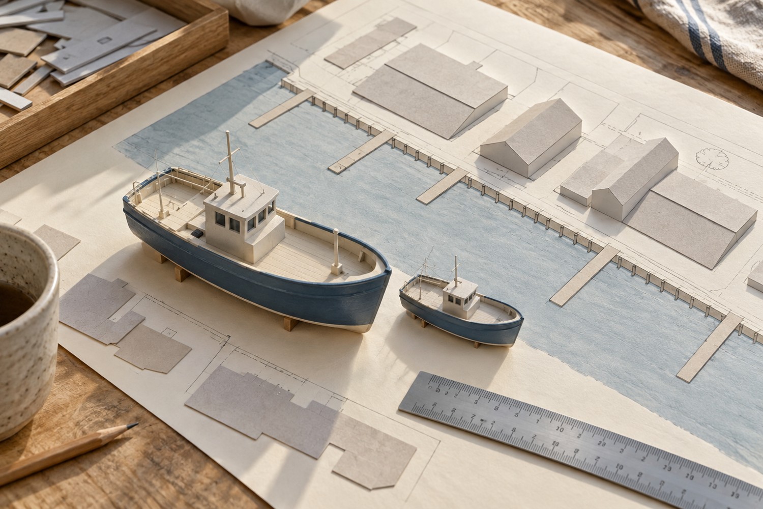
Choose a scale for a miniature harbour
Use the largest boat and the available footprint to choose a harbour scale before buying buildings and fittings.
Read article